Search
{:type=>"submit", :class=>"sr-only"}
Cars
Air
Boats
Free
You_Create
You_Create
You_Create
Upload your creations
You_See
Share videos & pictures
You_Meet
Create events
You_Chat
Forum
Join
Open main menu
Sign in
Sign Up
View all RC Car designs
YouMagine A Community Of RC Creators & Drivers
Open a Store
›
Full set for Cliffhanger
$27.00
RCNerds
SkeeRide 2
$30.00
Build It Better
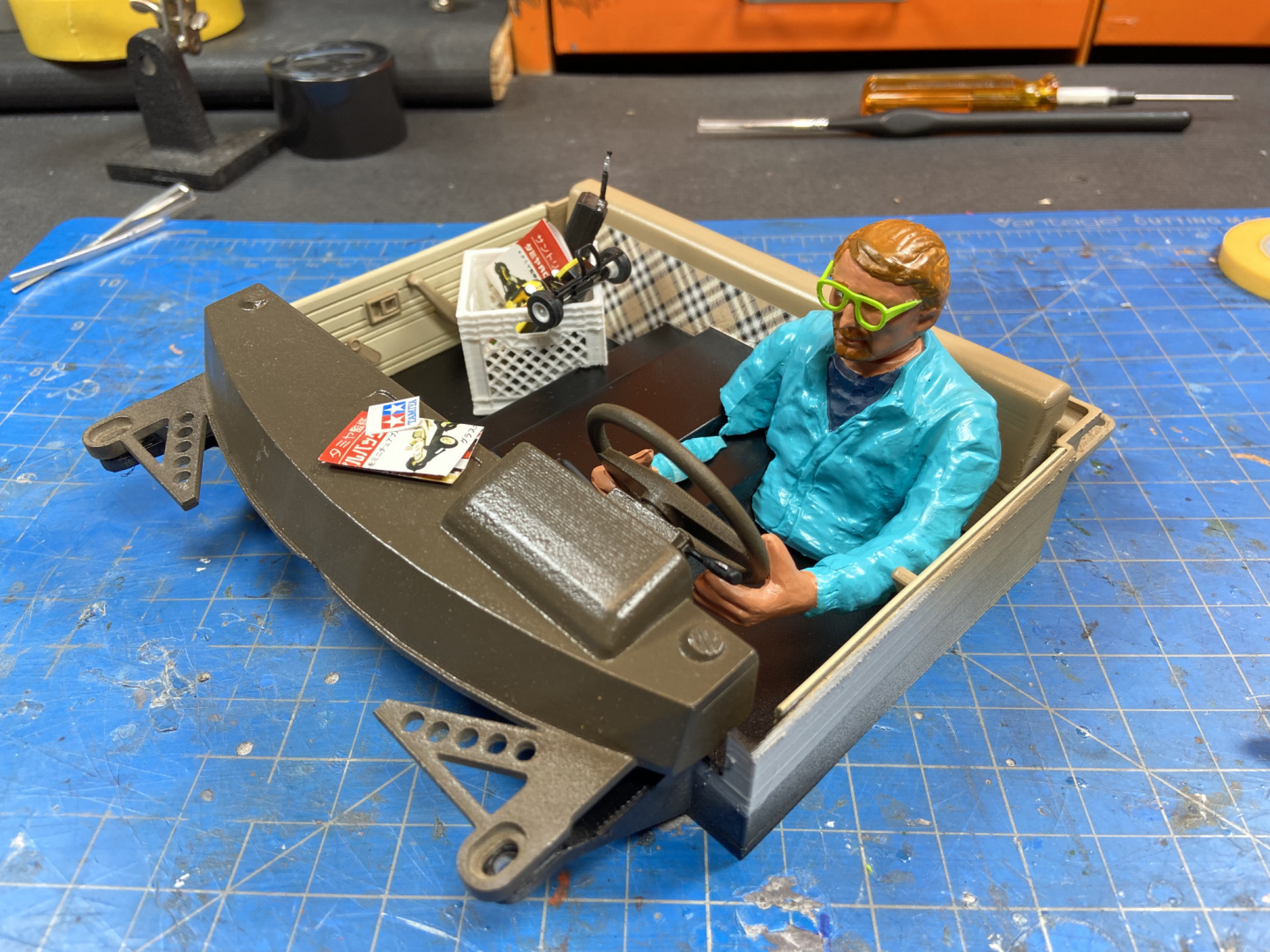
Tamiya Hilux High Lift Interior Set
$12.49
Ampro Engineering
SkeeRide 2 Polar
$30.00
Build It Better
Phoenix SEMA edition parts set
$19.99
Knight Customs
1/10 Hooni working drift interior
$19.99
Knight Customs
You_
The new You_ on mobile will come later this year.
Enjoy the RC community of 3D Creators and Drivers on desktop.
See You_ later!